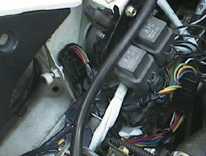
The new connectors are at the right, connected directly without the black box in between to maintain factory wiring.
In this step you will cut through your headlight actuator wiring and splice in two matching connectors. After this step is completed you should be able to plug the spliced-in new connectors together and restore stock headlight operation. The entire process will probably take about 1 to 3 hours per side. I recommend that you only work on 1 side at a time.
PreparationDe-energize the circuit. Verify the circuit is de-energized by placing the dash switch in the "down" position and turning the headlights on. If the headlights are on (they can be on in the up or down positions) or the actuators move, the system is not de-energized! Do not proceed.
To increase access, remove the headlight bezel (plastic shroud) from the headlight by removing four screws. Next locate the actuator engine: it is right below the manual actuator knob. Having located the actuator engine and its wiring, detach its wiring connector from its support by pushing it downwards. Take the connector apart by pressing in the retaining clip on the side and pulling. (On earlier Miatas, the upper part is also attached to the frame with two clips; reach behind it and push them together.)
Remove the electrical tape, and plastic cover from the body side (female connector) wiring for a length of about 8 inches. (See below for the color of the wires to cut.) Select the easiest spot in this wiring to cut the wires. Since you will be stripping these ends and soldering to them within the confines of the engine bay, (or crimping on connectors, if you must), you probably want to cut relatively close, but not too close, to the connector.
Check that the fuses are removed and cut the following 5 wires:
| 1993 & before | 1994 & after |
|---|---|
| Black | Black |
| Brown | Brown |
| White w/ Red stripe | Red w/ Green stripe |
| Green w/ Blue stripe | Green w/ Blue stripe |
| Red w/ Yellow stripe | Red w/ Yellow stripe |
Perform a best guess as to the lengths of your desired wiring paths from the actuator connector and chassis harness to where you want the extra connectors to be located. Disconnect the actuator connector. This should now come free from the car.
The first half of the new connectorTake the actuator connector to a suitable work space. Select the half of the new connector that has 5 pins and one hole. Set the other one (1 pin and 5 holes) aside. It will be installed on the car in the next part.
Cut the wires on the new connector about 1" longer than the desired length determined in part one. Select the colors to be spliced together as follows:
| 1993 & before | New Connector | 1994 & after |
|---|---|---|
| Black | Yellow | Black |
| Brown | Brown | Brown |
| White w/ Red | Blue | Red w/ Green |
| Green w/ Blue | Green | Green w/ Blue |
| Red w/ Yellow | Red | Red w/ Yellow |
Note that in this assembly the white wire on the new connector is not used. Cut it about 1-2" from the connector body.
Splice each wire on the new connector (5 male 1 female) to the actuator connector as described in the soldering section, using the colors listed above. (If you use crimp-on butt connectors, at least check that the connections are secure, and wrap the entire bundle very securely with electrical tape to take stress off the connections.)
The second half of the new connectorOut at the car, perform the above operations in the same way, with the following differences: Use the 5 holes and 1 pin portion of the connector. This way you can connect the two new connectors and everything should function normally. Don't cut or strip the white wire. This will be your connection to the left/right switch. Make sure you use the lengths determined in part 1 for the length of this connector (+1".)
Checking it so farCheck for any exposed wiring/solder connections up to the new connectors. If you've melted any shrink tubing or electrical tape, re-tape it to prevent shorts. If there are any pointy spots on any wire, remove the tape or shrink tubing, grind them smooth with sandpaper or a file, then re-tape them. This is the only real change to the car, and the only one you can't fix by removing the black box. Make sure it's right.
Make sure that the dashboard switch is in the "up" position. Verify that the fuses are removed, then connect the two new connectors and the factory actuator connectors. Re-install the headlight bezel with the 4 screws if removed. Make sure that all parts have ample free space and all wiring stays clear from the moving headlights, (including the bezels) and the actuator mechanism. Twist ties (garbage bag) could work for a temporary fix. Cycle the actuators down and up (by rotating the manual knob in the indicated direction only) and ensure there is no interference.
Now carefully re-energize the circuit by re-installing the fuses. (And reconnect the wiper motor connector if you took it off earlier.) Nothing should happen other than a click from the retractor relay telling the actuators that they should be up. Cycle the actuators using the dash switch, and by turning the headlights on and off. All circuits should operate as before.
If everything works as it should, proceed with the other side. Don't forget to pull the fuses again before proceeding.