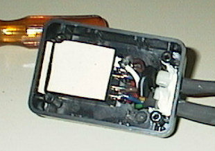
A look inside a black box.
The first thing you need to do is prepare the black boxes as per my wiring diagram. See the notes in the previous sections on parts and procedures on different ways to do this.
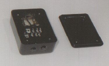
Modifying the Project EnclosuresFor the relay to fit properly, the boxes must be modified as follows:
For this step, I will refer to the two connectors as 5M1F (five male, one female) and 1M5F (one male, five female). The 5M1F connector will be connected to the chassis side connector in the car, and the 1M5F connector will be connected to the headlight actuator.

To determine the terminal numbers on the relay, take the second one and place it with the terminals up, so you can see the markings. Once you start installing wires, the markings become obscured, and using the drawing on the other end of the relay can be misleading. Make the second black box before closing the first to compare the two.
Trim the wiring connectors to the length decided upon (+ about 1") when determining where to put the black box. Trim the yellow and green wires about 1/2" shorter than this. Cut the white wire on the 1M5F connector about 2" from the connector. This wire is not used.
Using some of the scrap brown wire (about 1 3/4") make a jumper to be installed on the relay. Tin the ends, bend the ends into "U"'s and crimp but DO NOT solder this jumper onto terminals 3 and A of the relay yet.
For the remainder of this procedure, the parts should be laid out as follows: The box should be oriented with the two wiring holes on the left. The relay should have the A & B terminals closest to you. The 5M1F wires will be run through the top hole (farthest from you) in the box, and the 1M5F wires will be run through the bottom hole. Move the parts as necessary to facilitate soldering, but after each wire, place the components back in this position to keep everything straight.
Strip and tin the brown wire on the 5M1F connector and run it though the upper hole in the case. Bend it into a "U", and crimp it onto terminal 3 with the jumper installed above. Solder the connection.
Strip and tin the red wire from the 1M5F connector, run it through the lower hole, crimp and solder it to terminal 5. Strip and tin the brown wire from the 1M5F connector, crimp it next to the jumper on terminal A, and solder it in place.
Strip, tin, bend, crimp and solder the remaining connections in this order:
Re-check your wiring (i.e. connector/color to terminal number.) Look closely to ensure no solder connections between terminals are unusually close (< about 1/8"). If they are, the terminals can be carefully bent apart to provide more space, or a piece of electrical tape can be inserted between the terminals. All connections should be very tight (no wires can wiggle), and the wires should run directly away from the relay (not off to the side.) If any of the terminals are loose in the relay housing (probably from an overheated connection), chances are good that the relay is damaged and must be replaced.
Run the green wires through their corresponding holes, strip about 3/8" from each, splice, solder and tape the connection. Do the same with the yellow wire. Tape the yellow and green splices together.
Pull the connectors out of the box until the relay sits down flush in the bottom. The plastic cover should fit snugly now (make sure the notches you cut in the top are aligned correctly.)
Tightly wrap electrical tape along the wires from each connector as far up wires (toward the box) as possible.
Gently push the wires into the box (with the relay seated properly) and install a tie wrap tightly around each set of wires where they exit the box. This can be tricky, but is done to prevent an accidental yank of the wire from damaging the relay or silicone sealant.
Lift out the relay, and put a piece of foam tape on the under side, also put another piece on the top. You don't need to use both sticky sides of the tape (leave the plastic coating on one side.) The relay fits so snugly, it won't be bouncing around inside the box.
Put a generous amount of silicone aquarium sealer around the holes that the wiring goes through to make a watertight seal. Allow this to dry thoroughly. Be sure not to let it interfere with the top (trim any excess away.) With the amount of water blowing around in the vicinity of the headlights during driving in the rain, the black boxes MUST be watertight!
Put a piece of foam tape on the top of the relay, and install the top. The top should be very snug, but shouldn't be visibly bowed between the screws.
The black box is now ready for installation in the car.